RepRap controller
This is one of those projects I love to think back about although it turned out to be a bit of a fail.
The controller was used for controlling two fans (one for the stepper drivers, one for cooling the extruded filament) and the heated printbed of my RepRap Mendel so it had a thermistor input and an output that went to a power mosfet onto another board.
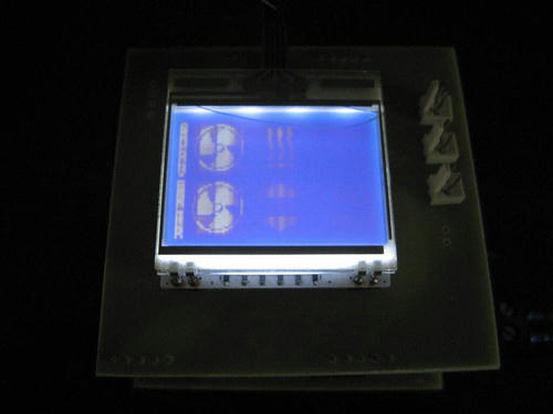
The MCU used was an Atmega88. The firmware just barely fit into it's program memory, which might be due to the fact that it had some fancy animations for the fans.
The display used was an EA DOGM128 with blue backlight and a resistive touch digitizer.
It had it all:
- Prototyping on a breadboard
- Programming
- Adapting the design to perfboard
- Making a PCB layout of it in KiCAD
- Printing it on a piece of copper via toner-transfer method
- Etching
- Drilling
- Soldering
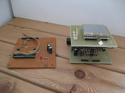
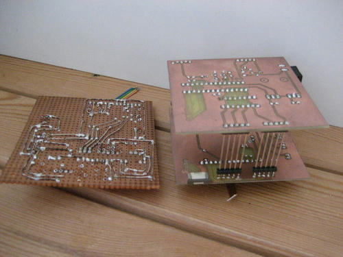
I chose to make a two-level/sandwich design, just so I could have a smaller footprint and I didn't have to worry about alignment or riveting vias in there.

An old friend of mine who is a chemist modified a laminating machine and set up a small PCB etching station in his labspace.
We only needed two attempts or so to figure out the chemical composition of the etching compound and etching time. It worked beautifully.
After drilling I quickly soldered everything together. You'll never know if it will work or if you made a small mistake somwhere in your PCB design. I can assure you the PCB design was fine. Some of the drill holes were a little off, but that was managable by bending the offending pins into compliance.

But wait.


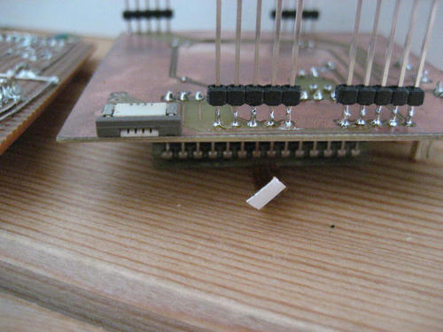
After realising I didn't consider the length of the touch screen digitizer's flat-flex cable, I got mad. One can see the exact point in time I got mad by looking at the 'finished' product. It was before soldering the last(!) connector on top. Nonetheless, to verify if my design worked I (mad-)soldered the sandwich pins. It did work, except for that tiny problem of the touch screen not sensing any touches.
There would have been ways to work around that, e.g. by desoldering the ZIF socket and attaching it with wires, but the whole point of the PCB etching was to not have wires flapping around that thing, so into the Archives it went...

Sadly you won't be able to admire it in it's full glory in this blogpost. At some point in time while being stored in my cellar the display fractured (must have been those ill tempered rats).
As of today, it has a comfortable place sitting on a shelve where it can do what it does best. Nothing.
It's the journey that counts, not the destination.